Tuesday, November 30, 2010
Bangbros Full Length Vedios Watch Now
Neighbors of the mother who drowned her son in Mahon  says it was strange."
child who drowned in the bathtub ..."
Murder View more presentations from manuel espinoza .
Thursday, November 4, 2010
How Long Does It Take Rpr

Rationalization Geometric
redraw the plant is streamlining its design project so inform the geometrically defined contours. will work through a combination of curved lines, circles defined from radio reported, and straight lines. You may establish other geometric references.
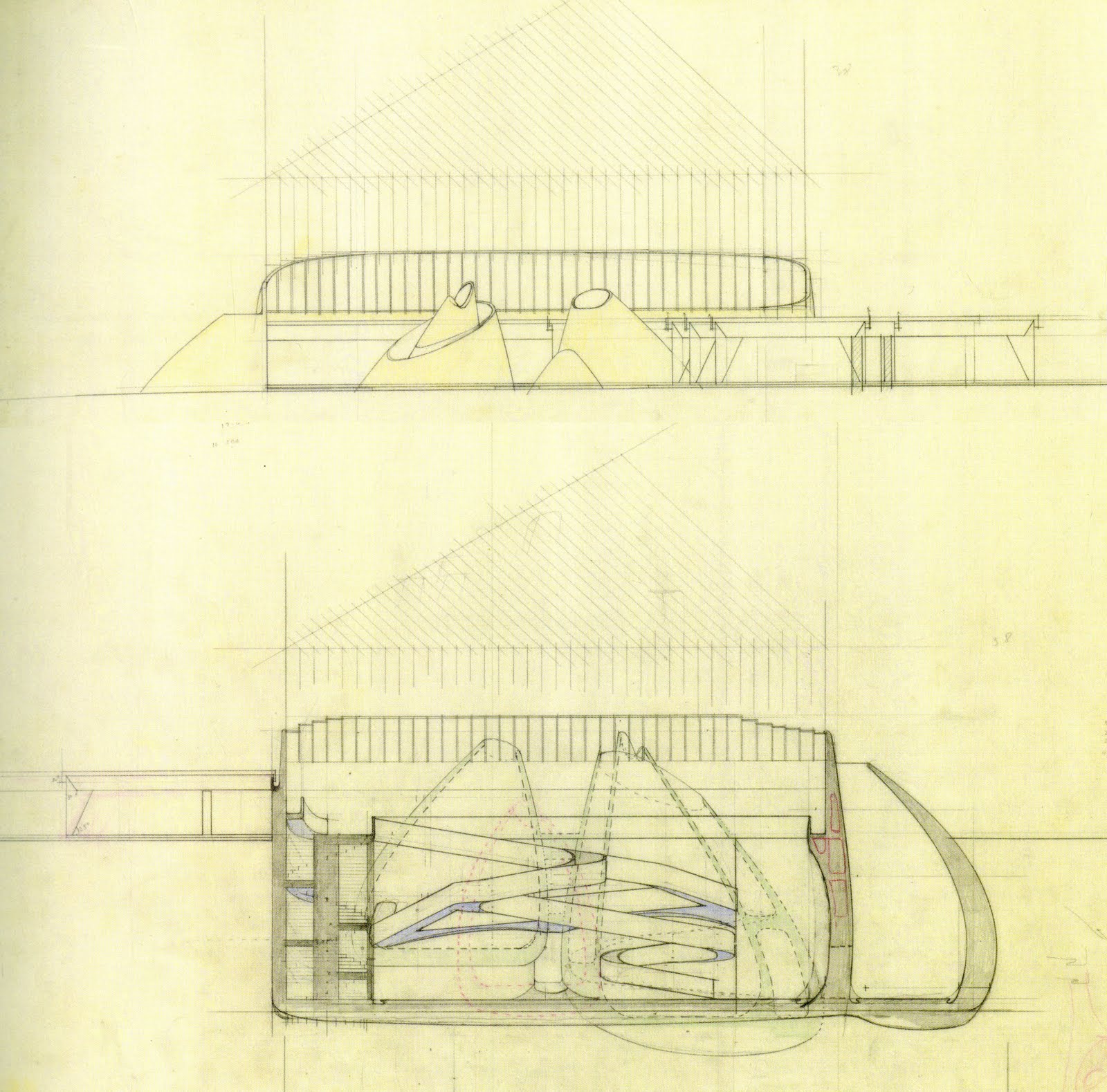
can be taken as the reference year of lifting a croissant Enric Miralles, who showed at the beginning of the workshop.
are asked to bring PLANT LAYOUT 1 / 100 or 1 / 75 The plant must be a plant that will enable anyone to reproduce the location of the project following the instructions geometric present in technical drawing.
ISOMETRIC 1 / 20 isometric line drawing of a significant portion of the project including construction elements being considered. of these building blocks calls include catalog items by 50% of the project, associated with a particular building component, either walls or roofs, or otherwise.
ARCHITECTURE surveying 1 / 100 and 1 / 50 are asked to update the base mapping project in the exercise of geometrical design of the plant, and following the instructions given drawing and representation on the task 8. NOTE: We will take as a reference or 'representation guide' file
GENERAL PLANIMETRIA.doc
SUMMARY SHEET be included in the photo of the skin animal, its rising and the relevant stages of project development.
Delivery
No note. Wednesday 10 November. 15:00 hrs. Chapel.
will work Wednesday 10 and Thursday 11 workshop sessions.
are asked to bring all the necessary computer, previous models, etc.


.jpg)
.jpg)


.gif)


Monday, November 1, 2010
How Can I Be A Waitress At A Strip Club
General Recommendations on planimetric

1. PLANT LOCATION (Scale 1:1000)
map geographical environment / urban project where AREA is clearly understood that the project is located. It is important to display more of a milestone which recognizes the area as a geographic feature near a building or street relevant.
The plan must include:
a) the streets and alleys
b) volumes of neighboring buildings,
c) vegetation (perimeter of the foliage of the larger species )
d) level heights (every 5 meters)
The project must be expressed to the profile that defines the plant roof and black. Also appear around the perimeter of the outer floor surface proposed by the project.
2. PLANT LOCATION
should see clearly the project's relationship with its immediate surroundings. Plant consists of a project, usually from ceiling level, inserted in a more detailed level environment that location.
The plan must include:
a) the streets, sidewalks and posts,
b) volumes of neighboring buildings, and farm boundaries
c) vegetation (perimeter of the foliage of all species),
d) soil texture (sand, dirt, pavement, water, etc.),
e) levels of level (every 1 meter)
f) parking
3. ARCHITECTURAL PLANTS
All plants of all floors of the project, cutting the level necessary to understand the total (not necessarily to 1.2 m as shown in the standard).
The elements cut by the plant, should be clearly distinguished through the thickness of the corresponding thick line (approximately 0.5) or the entire cut surface completely black. If only dealing thick lines correspond to structural elements as bearing walls and pillars. Nonstructural elements shall have a line slightly thinner.
Plants do not take people, nor are perspectives. If you include furniture, both fixed and mobile, in a line thickness 0.1. It is also recommended the use of cars, but please, that the models relate to the social context.
In those projects in which the sky is located above has some relevance (as a void volume or flown) will be represented by dashed line projection.
All plants should consider the immediate context, namely, dimensions of 1 m level (High), cut vegetation at the same height of the project (where appropriate, with the projection of upper foliage dotted line) and lower vegetation texture or soil type. Do not forget the location of the north.
The dimensions of the plants have suggested thick red 0.1, and must measure the widths major interior spaces, as the outer distance of larger volumes of the project. Caring for the size of the number as small as possible, and that the symbols of the extremes are clearly identifiable.
4. CORTES
All Cortes necessary for an understanding of the spatiality of the project. Each section was built from the path of a line across the main spaces on the ground. Therefore, the shafts or cut lines must be present in the plant architecture. Recommended in general cutting lines are parallel to the walls leading the project.
cut elements should be clearly distinguished through the thickness of the corresponding thick line (approximately 0.5) or the entire cut surface completely black. If only dealing thick lines correspond to structural elements as bearing walls and pillars. Nonstructural elements shall have a line slightly thinner.
The cuts will bring people, and are not perspectives. If you include furniture, both fixed and mobile, where the first line will have a thickness Mobile 0.2 and 0.1.
In the cuts does not project what is "behind" the cut line, but if you draw what is in front, beyond the cut line. Thickness is suggested to occupy 0.3 for the definition of bays or levels, and 0.2 for secondary members such as staircases, columns or windows, among others.
All courts should consider the immediate context, namely precise slopes, vegetation, soils of intermediate compounds, vertical closure of the land, etc.
The cuts should be clearly defined project's relationship with the natural soil. An alternative is that all the slopes, natural or constructed, are drawn with a thick line 0.7, which clearly note is changing the geometry and materiality of the soil. Another alternative is that the floor elements to express the detail of their material constitution, expressing the thickness of each of them (slabs, natural earth, tile, etc.).
Dimensions in cuts recommended only vertical axis, ie the cut is used to measure the heights and widths listed in plants.
5. RUNAWAYS CORTES
After that part of the project that is most distinctive about their spatial characteristics. The cuts include people escaped drawn as an outline only. If possible, escapees cuts are preferred include natural lighting.
6. CONSTRUCTION SEQUENCE
Small
consecutive images or animation of these, of all times relevant to the sequence of assembling a building or part of it. The binding of each new type of component or building element is a square. When many identical components, then the first table corresponds to the component and the second plane to define their units full. Do not forget foundations, windows, etc.. The sequence must be of an isometric view without perspective, and taken from the same focal point.
7. EXPLOITED ISOMETRIC
is a 3D design that separates the most important elements along its 3 planes, ie, both elements are operated in the vertical and horizontal axes in the 2. In general, the vertical axis is used to separate each level with each other, and horizontal rules to separate the constructive elements of each floor.
It is recommended that the structural elements on the vertical axis, and explode sideways components of the internal division on a horizontal axis and enclosing the components in the other
is suggested that the isometric angle is equal (isometric means equal measure) 30 °, the volumes are opaque (hidden line) and if the value of land (not render). Each element exploded close to another ought not, and it should be connected by dotted line.
* The morphology of each project suggest different interpretations of each of these guidelines.
8. GENERAL PROVISIONS
- ONLINE THICKNESS
in 1:500 scale projects, using two types of thickness. Between 2 and 3 of thickness for a) tide lines, b) roads c) outline of project volume. No. 1 thickness for all the rest.
- COTAS
All plans should come properly dimensioned. The measurements will be colored red, thin line, and with small numbers. The cuts will only measures the vertical axis. The plants will have measures in both axes and should indicate where to pass the cuts. In general, only narrow spaces most important, and let the dimension into the picture.
elevations will no bounds.
- FURNITURE
All plans include correct scale furniture. It is suggested that libraries share blocks of objects for the projects as realistic as possible.
Subscribe to:
Comments (Atom)